


Define the finish allowance before approving the first article for a 7075 aluminum thin-wall sleeve. This applies when a surface treatment or other finishing step may change a bore, outside diameter, face, or edge condition. Start by marking every treated surface on the drawing and stating whether each acceptance dimension applies before or after finishing. Without that basis, matching measurements can still describe different part conditions.
A visible line near a sleeve edge often starts the discussion, but appearance alone does not identify the cause. The line may be a turning witness on an untreated land, the boundary of a treated area, or a mark left by soft jaws. The drawing should connect the finish boundary to the functional geometry. For an instrument mount, the bore may locate a sensor body while the outside diameter seats in a bracket. If the finish covers one surface and stops short of the other, the supplier needs that boundary before planning stock, inspection, and masking. The buyer should also show whether the end face controls assembly depth and whether a short untreated land remains available as an inspection datum. Those details decide where the operator can hold the sleeve and where the inspector can place a contact without crossing the finish boundary.
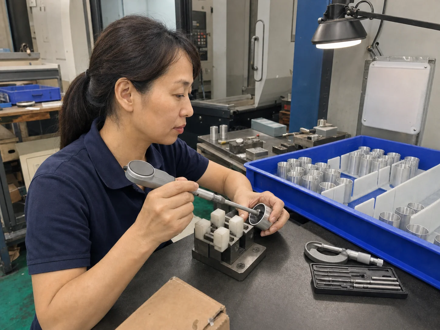
Thin walls make the measurement condition part of the evidence. The inspector supports each sleeve at the same datum, uses a gauge suited to the bore or outside diameter, and keeps contact force away from unsupported wall sections. She records the first piece before finishing and identifies the same feature for the post-finish check. A result taken while the sleeve sits in soft jaws cannot be compared directly with a released part unless the inspection plan approves both conditions. The record must name the support, contact location, and process stage.
Track finish allowance on the thin-wall sleeve drawing
The drawing needs two separate ideas: machining stock for a later operation and the final acceptance size. A finish allowance tells the machinist which surface needs material reserved or which dimension anticipates a later change. The final callout tells quality which condition must meet the assembly requirement. Combining both in one unexplained dimension forces the operator to infer the intended process. Mark the finish area, identify protected or untreated lands, and place the before-finish dimension beside its stage note. Put the final dimension with the post-finish acceptance method.
At a machine-side inspection bench, the quality inspector takes one sleeve from the work-in-process tray and rechecks the bore and outside diameter without exposing a fabricated reading. The approved first piece stays in a separate area, and mid-run samples retain their sequence. If the first piece and consecutive samples remain stable under one released-state method, CNC turning can continue on the current basis. If the apparent trend changes when the sleeve is rotated, moved to another contact point, or checked from a different datum, the team corrects the measurement setup before changing a tool offset.
Sample identity matters once finishing occurs outside the turning cell. The supplier should preserve the link between the as-turned sleeve and its later inspection record. A mixed tray of treated and untreated parts cannot show whether a dimensional change came from CNC turning, handling, the finishing step, or a different measuring method. Keep those conditions physically separated and label the process stage without adding customer data to the shop-floor card. The useful comparison pairs the same feature, datum, and released condition before and after finishing. Record which tray supplied each measurement and retain one accepted part from each condition. If a later result falls outside the expected relationship, quality can return to those physical samples and repeat the check. Unidentified loose parts cannot support a stage-by-stage decision because the team cannot connect the observed dimension to the operation that preceded it.
First-piece and consecutive-sample trends can reveal process movement, but they cannot predict an unspecified finishing result. A stable as-turned bore does not prove the final bore will meet the assembly requirement when the drawing omits the treated area or final inspection basis. The same limitation applies when the finish supplier controls masking, cleaning, or racking in a way the machining record does not capture. Engineering should define the interface before quality uses the turning trend as release evidence for the finished sleeve.
The supplier quality review should compare the drawing revision, process route, first-piece record, and one post-finish sample. Look for the same feature names and datum references in each document. Confirm that the treated surface shown on the drawing matches the surface visible on the sample. A dimension recorded only before finishing supports control of CNC turning. A final acceptance decision needs evidence from the stated finished condition. If the two records use different contact locations, repeat the measurement with one approved method before accepting or rejecting the process.
Before production release, add the finish area, before-and-after dimensions, and acceptance method to the thin-wall sleeve drawing. Then keep the approved first piece and consecutive CNC-turned samples separated during an in-process check. Continue the run when those samples remain stable under the stated datum and the post-finish sample meets the final condition. Stop and revise the allowance or process plan when the finished feature changes outside the drawing requirement even though the as-turned trend remains stable. Put the accepted check interval and sample locations in the process record so later batches use the same evidence basis instead of rebuilding the method from memory.