



Stop the release review when a C377 brass threaded sleeve gives different readings between inspectors. The sleeve may be sound, or one inspector may be touching a different thread flank, end face, or seating point. Define the gauge contact position on the drawing or work instruction, then repeat the first piece and consecutive samples at that location. If the results agree, the method caused the disagreement. If they still move, hold the parts and review the thread and shoulder condition.
A brass threaded sleeve used in an equipment adjustment mechanism usually has an internal thread, an outside diameter, and a face or shoulder that sets its installed position. Automatic lathe turning can produce those features in one sequence, but each feature gives the gauge a different reference. A thread plug that enters from the wrong end can stop on a chamfer instead of the working thread. A caliper placed across the sleeve can touch a burr or a soft edge. The inspection record should name the feature, the end, and the support used for each check.
This advice applies when the drawing defines the thread form, effective engagement, and inspection method. It does not settle fit, torque, pullout, or adjustment life when the mating shaft, housing, or fastener remains outside the released specification. It also does not prove a material problem from one variable reading. Before changing an offset or rejecting a batch, keep the first piece and an unchecked sample in separate trays, use the same gauge, and identify the physical contact point. The operator can then decide whether the variation follows the part or the inspection method.
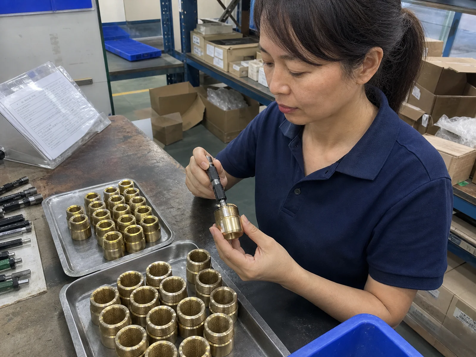
Where should the gauge touch the brass threaded sleeve?
The gauge should contact the feature that controls the equipment adjustment mechanism. For an internal thread, the inspector records the entry end, the start condition, and the stopping condition under the approved thread gauge method. For an outside diameter, she places the measuring faces at the defined axial section rather than searching along the sleeve for a preferred value. For a seating face, she supports the sleeve against the drawing datum and checks the face or shoulder that meets the mating component. The same contact position belongs on the first-piece record and the in-process sheet. Marking the contact section on a simple sketch can prevent a common handover error: one person measures near the end chamfer while another measures the working length. Those readings may both look plausible, yet they describe different parts of the geometry.
At the machine-side bench, the operator can separate a measurement disagreement from a turning problem with a short controlled sequence. She cleans the gauge contacts and the sleeve, checks the first piece at the marked location, and records the gauge identity beside the result. She repeats the check with the same support on two consecutive samples from the run. A second inspector then repeats the method without moving the reference sleeve. If both inspectors match on the reference and the production samples still differ, the team can inspect the thread flank, shoulder, or diameter for a real change. If the reference itself changes between people, the work instruction needs a clearer contact location.
Automatic lathe turning can leave several surfaces that look suitable for a measurement but do not answer the same question. A thread crest may carry a small tool witness while the flank remains usable. A chamfer can guide a gauge and make the start feel smooth even when effective engagement is short. A parting face can hold a burr that changes how the sleeve sits on a flat support. The inspector should record the observed surface and the condition that controls release. When a mark or burr sits outside the functional thread, the team should not label the whole sleeve defective without checking the drawing and the mating part. The shift handover should carry the same contact sketch or feature note as the inspection sheet. A new operator can then place the gauge at the marked section instead of copying a position from memory. If the drawing controls more than one thread or diameter, give each feature its own location and acceptance entry rather than asking one line on the form to cover the sleeve.
Handling between turning and inspection can add another source of disagreement. A tray divider may press the sleeve against one side, or a loose part may touch a thread opening and leave a chip. Keep checked and unchecked sleeves apart, retain one accepted first piece, and inspect the gauge before the next sample. The record should show the process stage, the sleeve identity, and the contact location. A related blind-hole thread check for brass knurled inserts explains why gauge depth and hole condition belong together. The same discipline helps here, but the sleeve still needs its own drawing and acceptance basis.
Repeat the first piece and consecutive samples with one method before approving a repeat run. Write the gauge contact location, support, entry end, and cleaning state into the inspection record. Continue when the reference sleeve and production samples agree at that defined point and the thread, shoulder, and outside surface meet the released drawing. Stop and revise the method when two inspectors obtain different results from the same reference, or when the samples move after the contact method is fixed. That result tells the buyer whether to correct the inspection instruction or review the turning and material condition.