



Define the treated and untreated surfaces of a 304 stainless precision bushing before approving a deburring route. If the drawing omits a finish allowance, an operator may remove material from a bore edge, shoulder, or face that controls a medical equipment mechanism. The first check should compare critical features before and after deburring on the same first piece. If the dimensions move outside the released condition, hold the sample and revise the drawing or process before quoting repeat work.
A precision bushing can guide a shaft, space a joint, or keep a sensor carrier aligned inside medical equipment. The bore controls the mating diameter, while an outside surface or shoulder may locate the bushing in a bracket. A small edge break can help assembly, yet a broad deburring pass can change the face that sets axial position. The drawing needs to identify the functional bore, outside diameter, shoulder, end face, and any edge that may receive manual or machine contact. Those feature names give the supplier a basis for separating a cosmetic mark from a dimension that controls fit.
A weak RFQ asks for a clean, burr-free bushing and leaves the finishing condition open. That language does not tell the supplier whether the released dimensions apply before deburring, after deburring, or after another surface operation. It also makes the first article hard to compare with a mid-run sample. Keep one as-turned bushing in a marked tray, record the critical features, run the planned deburring step, and measure the same features again. This sequence shows whether the process removes attached material without shifting the geometry that the assembly uses.
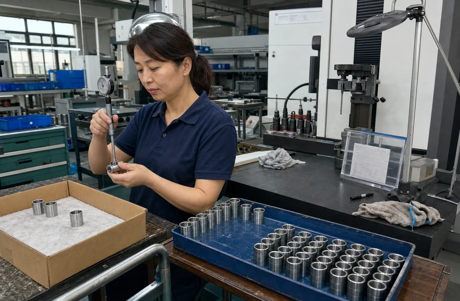
Which bushing surfaces need a finish allowance?
The allowance belongs beside the feature that changes during the selected finishing step. A bore entrance may need a controlled edge break while the working bore remains at its released size. A shoulder may need a burr removed while its seating face stays flat against the mating part. An outside diameter may tolerate a visual edge change but still control an interference or slip fit. Put the acceptance condition next to the feature, and state the process state in which the inspector records it. A general note at the bottom of the drawing cannot replace a clear instruction for each functional surface.
Deburring tools reach those surfaces in different ways. A hand scraper can follow an edge and remove a raised fragment, while an abrasive brush can touch a broader band around the bore. The operator should keep the tool contact on the approved edge and avoid crossing the datum face or working diameter. The record should identify the tool or method in plain language, the part support, and the surface checked. If a mark appears on the shoulder after deburring, the team can then compare the contact direction with the drawing rather than guessing whether the turning operation caused it.
First-piece evidence needs a fixed measurement sequence. The inspector cleans the gauge and bushing, checks the bore and outside diameter at the defined support, and records the shoulder or face condition before deburring. She then repeats the same checks after the part passes through the approved finishing step. A later sample from the run stays in a separate tray until the inspector measures it with the same method. If the first piece changes but the later samples hold that changed state, the drawing may describe the wrong process condition. If the mid-run sample moves again, the team should review tool contact, part support, and operator handling.
Material and geometry can make the visual result misleading. A 304 stainless bushing may show a bright line at an edge after a brush pass, yet the line may be a reflection rather than a removed section. A burr can hide at the intersection of the bore and shoulder while the outside wall looks clean. The inspector should record the location and use the approved light, support, and gauge for the comparison. Do not convert a clean appearance into a dimensional release when the drawing does not state whether the treated or untreated surface controls the decision.
Put the missing information into the RFQ before a supplier plans the route. Name the material condition, bore and outside diameter, shoulder datum, edge-break expectation, inspection method, and the process state for each dimension. State whether the buyer needs an as-machined record, a post-deburring record, or both. Weeda Precision can review that information with the part drawing, but the buyer still decides which face, bore, or edge controls the medical mechanism. Clear data also prevents a supplier from adding an unapproved secondary operation to make a vague “smooth finish” note look complete. Keep packing evidence separate from machining evidence. A tray divider or loose metal part can mark an edge after deburring, and a chip trapped in a bore can make a gauge seat differently at the next station. Place accepted first pieces in a protected location, keep unchecked bushings in a separate tray, and inspect the tray before loading the next group. If a face mark appears only after transfer, the handling path needs review. If the bore changes before transfer, compare the as-turned and deburred records before changing the workholding or tool.
The method has a boundary. Comparing dimensions before and after deburring can show a changed bore, shoulder, face, or edge condition, but it cannot establish fatigue life, sterilization performance, seal life, or medical-device validation without the released mating parts and test protocol. It also cannot prove that a supplier’s surface finish meets a separate coating or passivation requirement. Keep those acceptance questions in their own records. A correct finish allowance supports the dimensional decision, yet it does not replace the tests that the medical equipment assembly requires.
Before quoting repeat production, measure the critical bushing features before and after the planned finishing step. Continue when the bore, outside diameter, shoulder, and functional face remain within the released condition and the edge change matches the drawing. Stop and revise the drawing or process when the same feature moves after deburring, when the allowance is absent at a datum edge, or when consecutive samples disagree. The result tells the buyer whether to accept the present route, add a controlled allowance, or request a new first-piece confirmation.