


Stop the run when a 6061 aluminum thin-wall sleeve changes dimension after first article approval. Keep the approved first piece, a mid-run sample, and a sample after the machine stops in separate locations. Measure the bore and outside wall at the same released-state contact points, then compare the tool, support, and part-flow records. Matching measurements point to a stable process. A change after unclamping or tool use calls for a workholding, measurement, or tool review before more parts move forward.
An aluminum thin-wall sleeve can locate an instrument tube, protect a cable, or space a sensor inside an instrument mount. The bore may control the mating shaft while the outside wall fits a pocket or clamp. A thin section can spring back after a soft jaw releases it, and a tool mark can appear on one side without changing the opposite side. The drawing should identify the functional bore, outside diameter, end face, and any wall that the fixture supports. Those references let the inspector compare a part in the same state each time. The released condition should also state whether the sleeve rests on a flat support or hangs from a locating feature during measurement.
A first article proves that one sleeve met the drawing under one set of conditions. It does not prove that the support, tool edge, bar position, and measurement method remain unchanged through the run. A weak check measures a warm part on the fixture and compares that reading with a released sleeve at the bench. A stronger check labels the sample stage, lets the part reach the agreed inspection condition, and measures the same section before and after unclamping. If the bore moves after release, hold the parts while the team separates elastic recovery from tool wear.
Which contact points show real dimension drift?
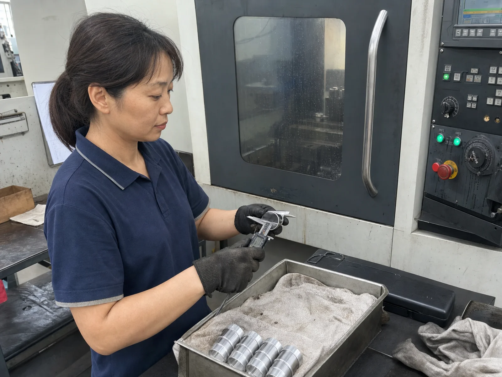
Start with the surface that controls the instrument mount. Place the bore gauge or suitable measuring tool at the defined axial section, with the sleeve supported in the released condition stated by the drawing. Check the outside wall at the location that meets the pocket or clamp, then check the end face that sets seating. Do not search along the sleeve for a smaller or larger reading. The record should name the contact point, support, part identity, and process stage so another inspector can repeat the same check.
The machine-side sequence should connect a dimension to the action that may change it. The operator keeps the safety door closed, checks the workholding after the machine stops, and records the active tool or support condition beside the sample. She places first-piece sleeves in one tray and mid-run sleeves in another. After a tool change or a jaw adjustment, she adds the next defined samples without mixing them with the accepted reference. If the first and mid-run sleeves agree before unclamping but separate after release, workholding or wall recovery deserves review. If both states move in the same direction, the team can inspect tool wear, part flow, or material position. Record the tool, measurement, and abnormal-sample information in one batch file with the drawing revision, material callout, support condition, measurement location, sample stage, and action taken after each comparison. If the pre-change and post-change samples line up at the same released-state contacts, the current route may continue. If the bore or outside wall moves after a jaw adjustment, keep the original reference and identify the new support condition before changing a machine offset.
Aluminum marks can confuse the visual review. A bright line may be a reflection from the tool path, while a shallow pressure mark may show where a jaw or tray touched the wall. The inspector should record the mark location and measure the bore and outside surface with the approved tool instead of treating appearance as proof. Keep abnormal sleeves in a closed tray and retain one sample from before the suspected change. Compare the same axial section on each sample, since a thin wall can vary along its length even when the end face appears unchanged. Note whether the part was supported at the bore, outside wall, or end face during each reading. A related locating-pin drift check shows why tool records and fixed measurement positions belong beside separated samples. A drawing review for finish allowance on a thin-wall sleeve covers a different surface condition, so it cannot replace the released-state check for this 6061 sleeve.
The method has a boundary. Separated samples and fixed contact points can show dimension drift, elastic recovery, tool influence, or measurement variation, but they cannot establish long-term fatigue life, vibration performance, coating behavior, or final instrument accuracy without the released assembly and test method. They also cannot prove that a wall mark came from the machine when the part passed through an unrecorded tray or outside process. Keep those questions in their own validation records. Before release, compare the first piece, the mid-run sample, and the post-change sample with one method. Continue when the released bore, outside wall, and end face agree and the records identify the same support and tool state for the released-state record. Stop and revise the route when consecutive samples move, a repeatable contact mark appears, or the measurement method cannot be reproduced. The result decides whether the batch file supports the current process or requires another first article review.